

MICROSCOPE AND THEIR TYPES
 cylinder
known as the Whenalt cap. This cap serves to shape the electron beam. Just
beyond the Whenalt cap is the anode which has an aperture through which the
electron beam passes. A large voltage is applied between the cathode (the tung.
sten filament) and the anode, this gives the electons their high velocity. The
wavelength of electron is inversely proportional to their velocity, and
therefore they have a very short wavelength (0.1-0.5A/ or 0.01-0.05 nm). The
electrons pass through the rest of the microscope without any further
acceleration.
cylinder
known as the Whenalt cap. This cap serves to shape the electron beam. Just
beyond the Whenalt cap is the anode which has an aperture through which the
electron beam passes. A large voltage is applied between the cathode (the tung.
sten filament) and the anode, this gives the electons their high velocity. The
wavelength of electron is inversely proportional to their velocity, and
therefore they have a very short wavelength (0.1-0.5A/ or 0.01-0.05 nm). The
electrons pass through the rest of the microscope without any further
acceleration.
The electron beam first passes through the condenser lens. As in the light microscope, this lens serves to focus the beam to the object, and so provides illumination. The lenses in the electron microscope consist of circular electromagnetic fields.
The magnetic lens of an electron microscope can have different powers (focal lengths and magnification) depending on the amount of current flowing through the electrical coils. In the light microscope, the lens powers are fixed, but the lenses are movable with respect to the object so that the image can be focussed and proper conditions of illumination obtained. In the elctron microscope, all the lenses are rigidly fixed, but their focal points are variable by changing lens currents. Thus, the illumination of the object is achieved by varying the current in the condenser lens.
The objective lens is placed with its focal point close to the object: Intermediate images are formed between each lens system. The projector throws its image on to a fluorescent screen (Fig. 3.28a) which
Essentially, the bright field microscope consists of a light source, a condenser that focuses rays of light on the specimen, a stage on which a specimen is placed, an objective lens that produces a magnified image of the objects in the specimen, and an eyepiece or ocular lens through which further magnified image of the object can be directly viewed. The specimen to be viewed with the light microscope has to be sufficiently thin so that light can pass through it.
Some light is absorbed while passing through the specimen, and a contrast may be produced due to differences in light absorption by different parts of the specimen. However, the optical system of the bright-light microscope does not reveal much contrast in the unstained preparation. Therefore, the contrast needs to be enhanced with staining. Terms and Principles commonly used in Microscopy
 Reflection
When a ray of light strikes a surface at an angle and it bounces back at an
angle of equal size, it is said to be reflected (Fig. 3.10). Reflection not
only occurs when light passes through air and strikes an object, but also when
it strikes an interface between air and glass. Stray reflections inside the
microscope interfere with the path of light rays and degrade the sharpness of
the image.
Reflection
When a ray of light strikes a surface at an angle and it bounces back at an
angle of equal size, it is said to be reflected (Fig. 3.10). Reflection not
only occurs when light passes through air and strikes an object, but also when
it strikes an interface between air and glass. Stray reflections inside the
microscope interfere with the path of light rays and degrade the sharpness of
the image.
 Refraction is simply the bending of
a light ray from the "normal" when it passes into a different optical
medium. A "normal" line is the line perpendicular to a flat surface.
Refraction is caused by changes in the speed of light while passing from one
medium into another of different optical density.
Refraction is simply the bending of
a light ray from the "normal" when it passes into a different optical
medium. A "normal" line is the line perpendicular to a flat surface.
Refraction is caused by changes in the speed of light while passing from one
medium into another of different optical density.
When light enters a more dense medium, it bends towards the normal line; when entring a less dense field, light bends away from the normal line (Fig. 3.11). Optical media include glass(such as lenses, filters, slides, coverslips), air, immersion oil, mounting medium etc.
Lenses in an optical system, the lens collect light rays from an object and redirects them to form a sharp, magnified image of the object in the image plane. There are two basic types of lenses used in microscopy-converging or positive lenses and diverging or negative lenses. The converging lens is convex and directs light to a point. The diverging lens is concave and it bends light outward. Several combinations of these two basic types are possible. However, double convex lens is the most common type used in microscopy.
Principle focus and optical center The center of lens surface on either side of a biconvex lens is called a center of curvature. A straight line joining these two centers is the principal axis. A ray of light entering the lens along the principal axis does not refract and travels along the same line. Rays of light entering a converging lens parallel to the principal axis, however, are refracted towards this axis. The point at which they meet is called the principal
 focus (F). A biconvex lens has a principle
focus on each side of the lens. A ray of light entering a converging lens at an
angle emerges parallel to the entering ray, and will pass through the center of
the lens. Another ray entering similarly from the other surface of the lens
also passes through the centre. The point at which these two rays cross is
called the optical centre (O) of the lens. The distance between the optical
centre and the principle focus is the focal length of the lens (Fig. 3.12).
focus (F). A biconvex lens has a principle
focus on each side of the lens. A ray of light entering a converging lens at an
angle emerges parallel to the entering ray, and will pass through the center of
the lens. Another ray entering similarly from the other surface of the lens
also passes through the centre. The point at which these two rays cross is
called the optical centre (O) of the lens. The distance between the optical
centre and the principle focus is the focal length of the lens (Fig. 3.12).
 Magnification The magnification produced by a lens
is defined as the ratio of the distance between the lens and the image plane
(b), and the distance between the lens and the object (a) as shown in Fig.
3.13.
Magnification The magnification produced by a lens
is defined as the ratio of the distance between the lens and the image plane
(b), and the distance between the lens and the object (a) as shown in Fig.
3.13.
The spherical aberration occurs when the edge of a lens gives a slightly higher magnification than its centre. This results in the loss of contrast, resolution, clarity and overall focus.
 Spherical aberration is a property of
those lenses that have less than perfect spherical shape and it increases with
increase in the thickness of the biconvex lens. It can be corrected by
compounding it with a biconcave lens that brings the image to a sharp focus.
Spherical aberration is a property of
those lenses that have less than perfect spherical shape and it increases with
increase in the thickness of the biconvex lens. It can be corrected by
compounding it with a biconcave lens that brings the image to a sharp focus.
 (e) The
stage is the platform on which the object is placed.
(e) The
stage is the platform on which the object is placed.
A circular hole in the centre of the stage allows light from below to pass through. A mechanical stage enables the specimen on the stage to be Moved in a controlled way. It holds the slide in place and moves it systematically either across or along the stage, by the rotation of two knobs, one for each direction. The knobs are usually located to one side of the stage. There may be a venire scale attached to the stage for each movement.
Fine adjustments- The high power objectives require fine focussing of the objects which is made possible with the fine adjustment. The fine adjustment is controlled by two smaller knobs, one on each side of the body. It moves the objective up and down slowly. In some models the fine adjustment is incorporated on the same knob as the coarse adjustment. In some microscopes the fine adjustment knob is graduated in microns to indicate the distance moved.
Condenser adjustments- The condenser has the features for focusing, adjustments of aperture iris diaphragm) and centering. It is usually focused up and down by rotating a knob attached to one side of it. The iris diaphragm which is just below the condenser is used to adjust the condenser aperture. It is made up of a number of leaves which can be opened and closed by moving a small projecting lever (Fig. 3.17).
Centering- Where the condenser is not permanently fixed, it can be centered to bring illuminating beam of light to strike accurately at the object.

The Lense Systems-
THE OBJECTIVE- The function of the objective is to produce a magnified image of the object. A light microscope has three or four objectives of varying magnifying power which are fitted on the revolving nose piece. Depending on the size of the object and the magnification required, any one of these objectives can be brought into the path of light by revolving the nose piece. Each objective is a complicated combination of lenses.
Magnifying Power of Objectives
Resolving Power
 3. Oil Immersion objective This is the objective with
highest magnification in the ordinary light microscope. It is marked 100 X, or
2 mm, or 1/12 inch. It is denoted by a white ring. This objective is always
used in conjunction with immersion oil. Oil, such as cedar wood oil, having the
same optical density as glass, is placed between the object and the lens to
eliminate refraction of light. The oil used for this purpose is called
immersion oil and it enables the light to pass in a straight line from glass
through the oil and back to the lens glass as though it were passing through
the glass all the way( Fig. 3.18).
3. Oil Immersion objective This is the objective with
highest magnification in the ordinary light microscope. It is marked 100 X, or
2 mm, or 1/12 inch. It is denoted by a white ring. This objective is always
used in conjunction with immersion oil. Oil, such as cedar wood oil, having the
same optical density as glass, is placed between the object and the lens to
eliminate refraction of light. The oil used for this purpose is called
immersion oil and it enables the light to pass in a straight line from glass
through the oil and back to the lens glass as though it were passing through
the glass all the way( Fig. 3.18).
Resolving Power
The limit of useful magnification is set by the resolving power of the microscope. Resolving power of the microscope objective is its ability to reveal closely adjacent points as separate and distinct. Quantitatively, it is a capacity to distinguish two neighbouring points as separate entities.
It depends largely upon the angle of light entering the objective and the refractive index of the medium between the object and the objective. The presence of oil between the object and the objective conserves many of the light rays which, would otherwise, have been lost by defraction.
Resolving Power ( 0.61 x 1
 This means
that the minimum distance between the two points, to be seen separate and
distinct, should be 200 nm (Fig. 3.19a). If it is less than this, they will
appear as a single object (Fig. 3.19b). When further magnification of the two
points fails to show them separate and distinct, it is called empty
magnification.
This means
that the minimum distance between the two points, to be seen separate and
distinct, should be 200 nm (Fig. 3.19a). If it is less than this, they will
appear as a single object (Fig. 3.19b). When further magnification of the two
points fails to show them separate and distinct, it is called empty
magnification.
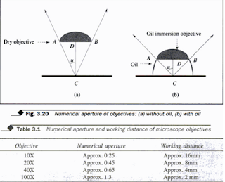
Numerical Aperture-The numerical aperture (NA) is defined as the product of the refractive index of the medium outside the lens (n) and the sine of half the angle of the cone of light absorbed by the front lens of the objective (u). This is expressed mathematically as
In modern microscopes, objectives are par-focal. This means that when an objective is used to focus on an object, the object will still be in focus with a small touch of the fine adjustment when another objective is swung into position. This prevents the possibility of damaging the object while changing from a low power to a high power objective during focussing. It also prevents the lens of the objective from being scratched.
The quality of an objective depends on how well it has been corrected. In most achromatic objectives, chromatic aberrations are corrected for two wavelengths while the spherical aberration is corrected for one wavelength. Achromatic objectives are most widely used in routine microscopy.
Types of Objective
Apochromatic lens (objective) is a highly corrected objective. These objectives are costly and are used mainly for research work. They are corrected for three spectral colours for chromatic aberrations, and two spectral colours for spherical aberrations. Apochromatic lenses are meant for oil immersion or high powered objectives and are
used in conjunction with a compensating eyepiece
Fluorite objectives are also known as semiapochromatic objectives. They are intermediate between achromatic and apochromatic objectives. The function of a fluorite objective is to correct the two types of aberrations for two wavelengths each,thus increasing the value of the numerical aperture for greater resolution.
The objectives are particularly useful in the visual or photographic recording of fine detailed demonstration of the tubercle bacilli following Ziehl-Neelsen staining. A 50X fluorite objective has a wider field than 100X oil immersion objective and a sharper image than a high power dry objective.
Flatfield (plano) objectives are corrected for field curvature. Additional lenses are built into this objective to flatten the image across the field so that the entire field is simultaneously focussed. Flatfield objectives are mainly used in photo-microscopy.
Types of Eyepieces
 Huygenian
eyepiece The most common type of eyepiece is the Huygenian eyepiece. It is
normally used with achromatic objective. It consists of two planoconvex lenses
of different sizes both facing the objective.
Huygenian
eyepiece The most common type of eyepiece is the Huygenian eyepiece. It is
normally used with achromatic objective. It consists of two planoconvex lenses
of different sizes both facing the objective.
1.The lens closer to the eye is called the eye lens and the other, field lens. At the focal plane of the eye lens, and between the two lenses, is the diaphragm (Fig. 3.21).
2. Rhamsden eyepiece This eyepiece also consists of two lenses, but instead of facing the objective as in Huygenian eyepiece,they face each other.
3. Compensating eyepiece This type of eyepiece is intended for use with apochromatic or fluorite objective, but not with achromatic objective.

4. Wide-field eyepiece This is used in association with flat field objectives. It is particularly useful when there is a need to scan a wide area of specimen.
5. Monocular and binocular microscopes A microscope with only one eyepiece is referred to as monocular microscope and one with two eyepieces is called a binocular microscope. In the modern binocular microscope, the rays of light reflected from the object are equally divided between the two eyepieces. This is achieved by the use of prism called the swan cube (Fig. 3.22).
The binocular microscope has the advantage over the monocular type that the image can be viewed with both eyes and therefore causes less strain to the eyes during long periods of microscopic work.
CONDENSER AND IRIS DIAPHRAGM
FILTERS
SOURCES OF ILLUMINATION (LIGHT)
KOHLER ILLUMINATION
MIRROR
TOTAL MAGNIFICATION OF A MICROSCOPE
11. If the objective lens is smeared or dirty, it should be cleaned with a clean piece of soft linen or lens tissue. Little xylene may be used if the dirt is difficult to remove. Never use alcohol because it can dissolve the cement used to keep the lenses together.
click on the micrscopy name if you want to know more about microscopes
MICROSCOPE
A
microscope, in simple terms, is an instrument used to view objects that are not
visible to the naked eye.
 |
| Add caption |
The
microscope is one of the most expensive and delicate instruments used in a
clinical laboratory. Because it can be easily misused, it is important for
medical laboratory personnel to be conversant with the working principle of the
commonly used light microscope, and should know how to use and maintain it
correctly.
cylinder
known as the Whenalt cap.
This cap serves to shape the electron beam. Just beyond the Whenalt cap is the anode which has an aperture through which the electron beam passes. A large voltage is applied between the cathode (the tung. sten filament) and the anode, this gives the electons their high velocity. The wavelength of electron is inversely proportional to their velocity, and therefore they have a very short wavelength (0.1-0.5A/ or 0.01-0.05 nm). The electrons pass through the rest of the microscope without any further acceleration.
This cap serves to shape the electron beam. Just beyond the Whenalt cap is the anode which has an aperture through which the electron beam passes. A large voltage is applied between the cathode (the tung. sten filament) and the anode, this gives the electons their high velocity. The wavelength of electron is inversely proportional to their velocity, and therefore they have a very short wavelength (0.1-0.5A/ or 0.01-0.05 nm). The electrons pass through the rest of the microscope without any further acceleration.
 cylinder
known as the Whenalt cap. This cap serves to shape the electron beam. Just
beyond the Whenalt cap is the anode which has an aperture through which the
electron beam passes. A large voltage is applied between the cathode (the tung.
sten filament) and the anode, this gives the electons their high velocity. The
wavelength of electron is inversely proportional to their velocity, and
therefore they have a very short wavelength (0.1-0.5A/ or 0.01-0.05 nm). The
electrons pass through the rest of the microscope without any further
acceleration.
cylinder
known as the Whenalt cap. This cap serves to shape the electron beam. Just
beyond the Whenalt cap is the anode which has an aperture through which the
electron beam passes. A large voltage is applied between the cathode (the tung.
sten filament) and the anode, this gives the electons their high velocity. The
wavelength of electron is inversely proportional to their velocity, and
therefore they have a very short wavelength (0.1-0.5A/ or 0.01-0.05 nm). The
electrons pass through the rest of the microscope without any further
acceleration.The electron beam first passes through the condenser lens. As in the light microscope, this lens serves to focus the beam to the object, and so provides illumination. The lenses in the electron microscope consist of circular electromagnetic fields.
The magnetic lens of an electron microscope can have different powers (focal lengths and magnification) depending on the amount of current flowing through the electrical coils. In the light microscope, the lens powers are fixed, but the lenses are movable with respect to the object so that the image can be focussed and proper conditions of illumination obtained. In the elctron microscope, all the lenses are rigidly fixed, but their focal points are variable by changing lens currents. Thus, the illumination of the object is achieved by varying the current in the condenser lens.
The imaging
system of the electron microscope usually consists of two lenses-the objective
and the projector lens. A third, intermediate lens, may be present between the
two.
This gives three stages of magnification and makes it possible to achieve high magnification in a reasonable amount of space. However, the numerical aperture of an electron microscope lens is very small and the best resolution is about 4 A i.e., 0.3 -0.5 nm (about 500 times better than that of light microscope which is 0.2 um).
This gives three stages of magnification and makes it possible to achieve high magnification in a reasonable amount of space. However, the numerical aperture of an electron microscope lens is very small and the best resolution is about 4 A i.e., 0.3 -0.5 nm (about 500 times better than that of light microscope which is 0.2 um).
The objective lens is placed with its focal point close to the object: Intermediate images are formed between each lens system. The projector throws its image on to a fluorescent screen (Fig. 3.28a) which
Working Principle of a Microscope..
The
microscope magnifies the image of the object being viewed through it. An
ordinary magnifying glass is referred to as a simple microscope, while a
laboratory microscope is referred to as a compound microscope, or a light
microscope, or more appropriately, a bright field microscope. The magnification
of the object is produced by the combined action of two lenses, the objective
lens near the object, and the eye piece lens near the viewer's eye.
Essentially, the bright field microscope consists of a light source, a condenser that focuses rays of light on the specimen, a stage on which a specimen is placed, an objective lens that produces a magnified image of the objects in the specimen, and an eyepiece or ocular lens through which further magnified image of the object can be directly viewed. The specimen to be viewed with the light microscope has to be sufficiently thin so that light can pass through it.
Some light is absorbed while passing through the specimen, and a contrast may be produced due to differences in light absorption by different parts of the specimen. However, the optical system of the bright-light microscope does not reveal much contrast in the unstained preparation. Therefore, the contrast needs to be enhanced with staining. Terms and Principles commonly used in Microscopy
Refraction is simply the bending of
a light ray from the "normal" when it passes into a different optical
medium. A "normal" line is the line perpendicular to a flat surface.
Refraction is caused by changes in the speed of light while passing from one
medium into another of different optical density. When light enters a more dense medium, it bends towards the normal line; when entring a less dense field, light bends away from the normal line (Fig. 3.11). Optical media include glass(such as lenses, filters, slides, coverslips), air, immersion oil, mounting medium etc.
Refractive Index It is the measure of refraction and
is measured as

Velocity in
medium (km/sec) It is proportional to the density of the medium. Refractive
index can also be defined as the relationship between the sine of the incident
angle (a) to the sine of the refracted angle (b).as shown in Figure 3.11.
Refractive
index of air is 1.0, of water is 1.3 and of glass is 1.5.

Lenses in an optical system, the lens collect light rays from an object and redirects them to form a sharp, magnified image of the object in the image plane. There are two basic types of lenses used in microscopy-converging or positive lenses and diverging or negative lenses. The converging lens is convex and directs light to a point. The diverging lens is concave and it bends light outward. Several combinations of these two basic types are possible. However, double convex lens is the most common type used in microscopy.
Principle focus and optical center The center of lens surface on either side of a biconvex lens is called a center of curvature. A straight line joining these two centers is the principal axis. A ray of light entering the lens along the principal axis does not refract and travels along the same line. Rays of light entering a converging lens parallel to the principal axis, however, are refracted towards this axis. The point at which they meet is called the principal
focus (F). A biconvex lens has a principle
focus on each side of the lens. A ray of light entering a converging lens at an
angle emerges parallel to the entering ray, and will pass through the center of
the lens. Another ray entering similarly from the other surface of the lens
also passes through the centre. The point at which these two rays cross is
called the optical centre (O) of the lens. The distance between the optical
centre and the principle focus is the focal length of the lens (Fig. 3.12).Magnification The magnification produced by a lens
is defined as the ratio of the distance between the lens and the image plane
(b), and the distance between the lens and the object (a) as shown in Fig.
3.13.
In simple
words, magnification is obtained by dividing the size of the image by the size
of the object. In case of a convex lens, the magnification is maximum when the
object is placed just outside the principal focus of the lens.
Defects in lens systems While lenses provide
the desirable aspect of magnification, they also have limitations caused by behavior
of light. In microscopy, these limitations arise from two causes-the shape of
the lens, and the presence of different wavelengths in the white light used.
These limitations give rise to two defects, namely, spherical aberration and chromatic aberration. These two aberrations are corrected by compounding lenses of varying refractive indices and dispersing abilities to one compound lens.
These limitations give rise to two defects, namely, spherical aberration and chromatic aberration. These two aberrations are corrected by compounding lenses of varying refractive indices and dispersing abilities to one compound lens.
Spherical
aberration is the indistinct or fuzzy appearance of images due to nonconference
of rays of light to a common focus (Fig 3.14).
The spherical aberration occurs when the edge of a lens gives a slightly higher magnification than its centre. This results in the loss of contrast, resolution, clarity and overall focus.
Spherical aberration is a property of
those lenses that have less than perfect spherical shape and it increases with
increase in the thickness of the biconvex lens. It can be corrected by
compounding it with a biconcave lens that brings the image to a sharp focus.
Chromatic
aberration is defined as the fuzzy appearance of the image due to
non-convergence of rays of white light to a common focus. This is the condition
in which the image is surrounded by a multi-colored fringe, with the blue light
being slightly more magnified than the red.
It is caused by splitting of white light into its component colours while passing through a biconvex lens, which acts as a prism. When white light passes through a prism, the light of shorter wavelength, like blue (wavelength 350 nm), is refracted more strongly than that of a longer wavelength such as red (wavelength 700 nm).
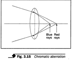 Thus, the light of one
colour is projected at a greater magnification than another resulting in the
appearance of coloured fringes in the image of the object (Fig. 3.15).
Thus, the light of one
colour is projected at a greater magnification than another resulting in the
appearance of coloured fringes in the image of the object (Fig. 3.15).
Chromatic aberration in modern microscopes is controlled by proper combination of lenses. Achromatic lenses are corrected for one colour while the apochromatic are for three colours.
It is caused by splitting of white light into its component colours while passing through a biconvex lens, which acts as a prism. When white light passes through a prism, the light of shorter wavelength, like blue (wavelength 350 nm), is refracted more strongly than that of a longer wavelength such as red (wavelength 700 nm).
Thus, the light of one
colour is projected at a greater magnification than another resulting in the
appearance of coloured fringes in the image of the object (Fig. 3.15). Chromatic aberration in modern microscopes is controlled by proper combination of lenses. Achromatic lenses are corrected for one colour while the apochromatic are for three colours.
COMPONENTS OF A MICROSCOPE
Basically, a
microscope is made up of three parts:
1. The stand
which is a support for all the other parts
2. The
mechanical components
3. The lens
systems Figure 3.16 illustrates parts of a binocular microscopes.
The
Microscope Stand The stand is the framework of the microscope. It comprises the
following:
(a) The tube
which holds the objectives and the eyepiece. For most laboratory microscopes
three or more objectives are needed and these are screwed into the revolving
nose piece. The eyepiece can either be monocular or binocular. It is inserted
the upper end of the tube.
(b) Tube
length of a microscope is the distance between the eyepiece and objective.
(c) The body
of the microscope supports the focusing mechanisms.
(d) The arm
gives correct frame to the tube and the body.
 (e) The
stage is the platform on which the object is placed.
(e) The
stage is the platform on which the object is placed.A circular hole in the centre of the stage allows light from below to pass through. A mechanical stage enables the specimen on the stage to be Moved in a controlled way. It holds the slide in place and moves it systematically either across or along the stage, by the rotation of two knobs, one for each direction. The knobs are usually located to one side of the stage. There may be a venire scale attached to the stage for each movement.
(F) The sub
stage is immediately below the stage and holds the condenser with its iris
diaphragm and a holder for light filter.
(g) The foot or the base may be in the form of
a large block or horse shoe shape. It enables the microscope to sit firmly on
the bench.
The Mechanical Components
The
mechanical components include: Coarse adjustments The coarse adjustment is
controlled by the rack and pinion mechanism manipulated by a pair of large
knobs one on each side of the body of the microscope. By rotating these knobs,
the tube with its lenses moves up and down fairly rapidly. It is used for rough
focussing which is often enough for low power objectives.
Fine adjustments- The high power objectives require fine focussing of the objects which is made possible with the fine adjustment. The fine adjustment is controlled by two smaller knobs, one on each side of the body. It moves the objective up and down slowly. In some models the fine adjustment is incorporated on the same knob as the coarse adjustment. In some microscopes the fine adjustment knob is graduated in microns to indicate the distance moved.
Condenser adjustments- The condenser has the features for focusing, adjustments of aperture iris diaphragm) and centering. It is usually focused up and down by rotating a knob attached to one side of it. The iris diaphragm which is just below the condenser is used to adjust the condenser aperture. It is made up of a number of leaves which can be opened and closed by moving a small projecting lever (Fig. 3.17).
Centering- Where the condenser is not permanently fixed, it can be centered to bring illuminating beam of light to strike accurately at the object.
The Lense Systems-
The
microscope lense system, which is also referred to as optics of the microscope,
comprise the objective, the eyepiece, the condenser and the light source. A
mirror may be necessary to direct an external light source to the object.
THE OBJECTIVE- The function of the objective is to produce a magnified image of the object. A light microscope has three or four objectives of varying magnifying power which are fitted on the revolving nose piece. Depending on the size of the object and the magnification required, any one of these objectives can be brought into the path of light by revolving the nose piece. Each objective is a complicated combination of lenses.
Magnifying Power of Objectives
1. Low power
objective this can be identified by such markings as 10 X, or 16 mm, or 2/3 inch.
This objective can also be coded with a yellow ring. The objective is generally
used for rapid scanning of the microscopic field.
2. High dry
objective this objective is marked 40 X, or 4 mm, or 1/6 inch. The color code
is blue ring. This objective gives highest magnification in dry objectives.
3. Oil
Immersion objective this is the objective with highest magnification in the
ordinary light microscope. It is marked 100 X, or 2 mm, or 1/12 inch. It is
denoted by a white ring. This objective is always used in conjunction with
immersion oil.
Oil, such as
cedar wood oil, having the same optical density as glass, is placed between the
object and the lens to eliminate refraction of light. The oil used for this
purpose is called immersion oil and it enables the light to pass in a straight
line from glass through the oil and back to the lens glass as though it were
passing through the glass all the way( Fig. 3.18).
Resolving Power
The limit of
useful magnification is set by the resolving power of the microscope. Resolving
power of the microscope objective is its ability to reveal closely adjacent
points as separate and distinct. Quantitatively, it is a capacity to
distinguish two neighboring points as separate entities. It depends
2. High dry
objective This objective is marked 40 X, or 4 mm, or 1/6 inch. The colour code
is blue ring. This objective gives highest magnification in dry objectives.
 3. Oil Immersion objective This is the objective with
highest magnification in the ordinary light microscope. It is marked 100 X, or
2 mm, or 1/12 inch. It is denoted by a white ring. This objective is always
used in conjunction with immersion oil. Oil, such as cedar wood oil, having the
same optical density as glass, is placed between the object and the lens to
eliminate refraction of light. The oil used for this purpose is called
immersion oil and it enables the light to pass in a straight line from glass
through the oil and back to the lens glass as though it were passing through
the glass all the way( Fig. 3.18).
3. Oil Immersion objective This is the objective with
highest magnification in the ordinary light microscope. It is marked 100 X, or
2 mm, or 1/12 inch. It is denoted by a white ring. This objective is always
used in conjunction with immersion oil. Oil, such as cedar wood oil, having the
same optical density as glass, is placed between the object and the lens to
eliminate refraction of light. The oil used for this purpose is called
immersion oil and it enables the light to pass in a straight line from glass
through the oil and back to the lens glass as though it were passing through
the glass all the way( Fig. 3.18).Resolving Power
The limit of useful magnification is set by the resolving power of the microscope. Resolving power of the microscope objective is its ability to reveal closely adjacent points as separate and distinct. Quantitatively, it is a capacity to distinguish two neighbouring points as separate entities.
It depends largely upon the angle of light entering the objective and the refractive index of the medium between the object and the objective. The presence of oil between the object and the objective conserves many of the light rays which, would otherwise, have been lost by defraction.
Resolving Power ( 0.61 x 1
NA where 2
is the wavelength of light used and NA is the numerical aperture. For green
light, where lambda is approx. 540 nm, and numerical aperture of the lens used
is 1.4, the resolving power is about 200 nm (0.2um).
 This means
that the minimum distance between the two points, to be seen separate and
distinct, should be 200 nm (Fig. 3.19a). If it is less than this, they will
appear as a single object (Fig. 3.19b). When further magnification of the two
points fails to show them separate and distinct, it is called empty
magnification.
This means
that the minimum distance between the two points, to be seen separate and
distinct, should be 200 nm (Fig. 3.19a). If it is less than this, they will
appear as a single object (Fig. 3.19b). When further magnification of the two
points fails to show them separate and distinct, it is called empty
magnification.Numerical Aperture-The numerical aperture (NA) is defined as the product of the refractive index of the medium outside the lens (n) and the sine of half the angle of the cone of light absorbed by the front lens of the objective (u). This is expressed mathematically as
Figure 3.19
shows NA objective with-out oil The refractive index of air is 1 while that
has a higher NA then any objective
Some
objectives have the numerical aperture engraved on them. The numerical
apertures of the commonly used objectives are shown in Table 3.1 below.
The
numerical aperture is in many ways more important than the magnification. This is
because an increase in NA results in an increase in resolution.

Focal Length
and Working Distance
The focal
length of a lens is the distance between the optical centre and the point at
which the parallel rays of light passing through it come to a critical focus.
Since it is not possible to determine the exact optical centre of the
objective, the term equivalent focal length is used.
The focal length, however, is of less practical value than the working distance which is the distance between the front lens of the objective and the object in focus. The working distance is much less than the focal length and it is of practical importance, especially with high power objectives where the use of a wrong working distance can result in the damage to the front lens of the objective. To reduce such damage to a minimum, spring loaded objectives are in use.
The focal length, however, is of less practical value than the working distance which is the distance between the front lens of the objective and the object in focus. The working distance is much less than the focal length and it is of practical importance, especially with high power objectives where the use of a wrong working distance can result in the damage to the front lens of the objective. To reduce such damage to a minimum, spring loaded objectives are in use.
In modern microscopes, objectives are par-focal. This means that when an objective is used to focus on an object, the object will still be in focus with a small touch of the fine adjustment when another objective is swung into position. This prevents the possibility of damaging the object while changing from a low power to a high power objective during focussing. It also prevents the lens of the objective from being scratched.
Double
achromatic lens is a composite of two lenses used to correct spherical and
chromatic aberrations in the lens. The first lens is a convex lens and is of
crown glass, and the other is a concave lens and is made of flint glass.
The quality of an objective depends on how well it has been corrected. In most achromatic objectives, chromatic aberrations are corrected for two wavelengths while the spherical aberration is corrected for one wavelength. Achromatic objectives are most widely used in routine microscopy.
Types of Objective
Apochromatic lens (objective) is a highly corrected objective. These objectives are costly and are used mainly for research work. They are corrected for three spectral colours for chromatic aberrations, and two spectral colours for spherical aberrations. Apochromatic lenses are meant for oil immersion or high powered objectives and are
used in conjunction with a compensating eyepiece
Fluorite objectives are also known as semiapochromatic objectives. They are intermediate between achromatic and apochromatic objectives. The function of a fluorite objective is to correct the two types of aberrations for two wavelengths each,thus increasing the value of the numerical aperture for greater resolution.
The objectives are particularly useful in the visual or photographic recording of fine detailed demonstration of the tubercle bacilli following Ziehl-Neelsen staining. A 50X fluorite objective has a wider field than 100X oil immersion objective and a sharper image than a high power dry objective.
Flatfield (plano) objectives are corrected for field curvature. Additional lenses are built into this objective to flatten the image across the field so that the entire field is simultaneously focussed. Flatfield objectives are mainly used in photo-microscopy.
Spring
loaded objectives are found in modern microscopes and are made to protect the
specimen and the front lens of the objective from being damaged during
focussing. The front mount of the objective pushes in when pressed against the
slide.
THE EYEPIECE OR THE OCULAR SYSTEM
The eyepiece
lens magnifies the primary image produced by the objective lenses and presents
the final image of the object to the eye. The range of eyepiece magnification
availble is 5X, 7X, 10X, 15X or 20x.
The eyepiece with higher power gives greater magnification, but a brighter and sharper image is obtained with a low power eyepiece. Therefore, 10X eyepiece is the most commonly used eyepiece. Some eyepieces have built-in pointers so that specific features within the field of view may be indicated. This is especially useful for teaching purposes.
The eyepiece with higher power gives greater magnification, but a brighter and sharper image is obtained with a low power eyepiece. Therefore, 10X eyepiece is the most commonly used eyepiece. Some eyepieces have built-in pointers so that specific features within the field of view may be indicated. This is especially useful for teaching purposes.
Types of Eyepieces
Like the
objective, the eyepiece is also a complex system of more than one lenses.
Depending on the arrangement and type of lenses used, they can be described as:
Huygenian
eyepiece The most common type of eyepiece is the Huygenian eyepiece. It is
normally used with achromatic objective. It consists of two planoconvex lenses
of different sizes both facing the objective. 1.The lens closer to the eye is called the eye lens and the other, field lens. At the focal plane of the eye lens, and between the two lenses, is the diaphragm (Fig. 3.21).
2. Rhamsden eyepiece This eyepiece also consists of two lenses, but instead of facing the objective as in Huygenian eyepiece,they face each other.
3. Compensating eyepiece This type of eyepiece is intended for use with apochromatic or fluorite objective, but not with achromatic objective.
4. Wide-field eyepiece This is used in association with flat field objectives. It is particularly useful when there is a need to scan a wide area of specimen.
5. Monocular and binocular microscopes A microscope with only one eyepiece is referred to as monocular microscope and one with two eyepieces is called a binocular microscope. In the modern binocular microscope, the rays of light reflected from the object are equally divided between the two eyepieces. This is achieved by the use of prism called the swan cube (Fig. 3.22).
The binocular microscope has the advantage over the monocular type that the image can be viewed with both eyes and therefore causes less strain to the eyes during long periods of microscopic work.
A trinocular
head attachment is an inclined binocular eyepiece with a third protruding tube
and sliding prism. This additional tube is used for attaching a camera for
photomicrographic work.
6. Measuring
eyepiece An eyepiece fitted with a disc which has a scale on it (graticule) is
called a measuring or micrometer eyepiece. By adjusting the upper lens, the
graticule can be sharply focussed on the object.
The
measurement of each division of the graticule for each objective can be
calculated by using a stage micrometer which is a measured scale. Details of
measurement of the object using calibrated eyepiece scale are given later under
micrometry.
CONDENSER AND IRIS DIAPHRAGM
The
condenser is a large lens mounted below the stage, with the iris diaphragm
below it. It consists of two or three lenses, and allows light to pass through
to the objective at a sufficiently wide angle to illuminate the object
uniformly at the point of focus. It supplies the object with a cone of light of
correct size and character in order to achieve the maximum performance of the
system.
Abbe
condenser For ordinary transmitted light microscopy, the Abbe condenser is
mostly used. The illumination it provides is called Abbe illumination. It is
made of two large planoconvex lenses separated by a layer of air and are
provided with an adjustible iris diaphragm that is mounted at the back focal plane
of the lens. Optically speaking it
is most
efficient and it is easy to use since it does not require to be focused or centered.
It is employed where high performance is essential.
Condenser
aperture The condenser, like the objective, has numerical aperture (NA). This
NA is the angle of the cone of light that passes from it through the object on
to the objective. The full NA of the objective can only be achieved if the
condenser supplies a solid cone of light of similar aperture.
The NA of the objective, therfore, should match the NA of the condenser. Using too large a condenser aperture, however, results in the production of a glare (too much light entering through the condenser up to the eye of the observer) which distorts the image of the object.
The NA of the objective, therfore, should match the NA of the condenser. Using too large a condenser aperture, however, results in the production of a glare (too much light entering through the condenser up to the eye of the observer) which distorts the image of the object.
The iris
diaphragm is used to regulate the angle of cone of light entering the
condenser.
Condenser
with a swing-out upper lens This type of condenser has a top upper lens which
can be swung aside when a low power objective is used. It thus makes it
possible for light to fill a much larger field of view of low power objective.
The substage may be lowered slightly.
Aplanatic condenser When an Abbe condenser is
found to be inadequate, the aplanatic condenser is usually the answer. It is
well corrected for spherical aberration.
Achromatic
condenser This type of condenser is corrected for both chromatic and spherical
aberration. It is mainly used for critical work. It is very expensive.
FILTERS
Light
filters are required in the microscope for sev. eral reasons, such as:
1. To reduce
the brilliance or intensity of light For example, neutral grey filter.
2. To
increase contrast and resolution. For example, blue and green filters.
3. To adjust
the colour balance of light to give the best visual effect.
4. To
provide monochromatic light when required.
5. To absorb
heat from the high intensity lamps.
6. To
transmit light of a selected wavelength. or example, an exciter filter used in fluorescence
microscopy.
7. To
protect the eye from injury by ultravioletrays. For example, barrier filter
used in fluorescence microscopy.
SOURCES OF ILLUMINATION (LIGHT)
The source
of light often depends on whether electric current is available or not, and
whether the microscope is being used in day time or after dark. It is
important, however, that no matter the source, the light should fill the field
of view and fill the whole of the back lens of the objective so that the image
can be properly viewed.
Daylight Direct sunlight is not very good for
the microscope and the eye. It is best to use reflected day light. This is
sufficient for use with monocular microscope and it is too weak for use with
oil immersion objective.
Electric
light For most routine work, a 60 watt electric bulb placed about 45 cm from
the microscope is an adequate source of illumination. Quartz halogen and
tungsten lamps are widely used. Many modern microscopes, especially the
binocular ones, are provided with a built-in source of illumination.
Battery lamp
In the absence of electric light, a 6 volt microscope lamp can be connected to
a 6 volt battery. This needs to be used through a transformer.
KOHLER ILLUMINATION
In the past,
microscopists talked about critical illumination which is today referred to as
Kohler illumination. Kohler illumination gives the highest possible resolution
and useful magnification to any objective. Thus it provides uniform
illumination which just fills the field of view of the eyepiece.
Requirements for Kohler Illumination
1. A lamp of
high intensity but of small light emitting area mounted on a centring mount or
some pre-focus mount to ensure that the centre of the filament is on the
optical axis of the lamp.
2. A
focussable lamp condenser with a multilens system to correct the basic
aberrations.
3. An
adjustible iris diphragm.
-To Set up Kohler Illumination
1. Focus on
the specimen with the lower power objective.
2. Raise the
condenser to its highest position.Close the iris diaphragm. Move the condenser
down until an image of the iris diaphragm appears.
3. Bring the
centre of the circle of light to the centre, using the condenser centring
screws.
4. Open the
iris diphragm slowly till the circle of light fills the entire field.
5. Remove an
eyepiece, and adjust the iris
diaphragm to
cover 75 per cent of the illuminated circle. This represents the objective lens
aperture. Replace the eyepiece and continue microscopy.
MIRROR
In
microscopes without a built-in source of illumination, a mirror is placed below
the condenser and iris diaphragm. It is circular and will stay in place when
turned in any direction. It reflects the beam of light from the source through
the iris into the condenser. It usually comprises two mirrors mounted back to
back, with one being flat and the other concave. The concave side is not to be
used with the condenser; it is only the flat side that is used in conjunction
with the condenser.
TOTAL MAGNIFICATION OF A MICROSCOPE
In the
compound microscope, the magnified image is produced by two sets of lenses-the
objective and the eyepiece. The objective produces a real, magnified, inverted
image of the object which is brought into focus by the field lens of the
eyepiece. This primary image when viewed by the eye lens is within the focal
length of the lens and a magnified virtual image is produced (Fig. 3.23).
The total
magnification of the microscope is thus the magnification of the objective
multiplied by that of the eyepiece. For example, using a 40X objective and a
10X eyepiece, the object will be magnified 400 times. If a 100X objective is
used with a 10X eyepiece, it will give an increased magnification of 1.000X.
When this increased magnification results in bringing further details of the object into view, it is called useful magnification. If the enlargement of the object fails to bring into view any more detail, and looses the sharpness of the image, it is called empty magnification (Fig. 3.19b).
When this increased magnification results in bringing further details of the object into view, it is called useful magnification. If the enlargement of the object fails to bring into view any more detail, and looses the sharpness of the image, it is called empty magnification (Fig. 3.19b).
Resolving
power of the microscope plays a major role in increasing the useful
magnification of the microscope. It should be noted that because of the
combined action of both the lens systems of the compound microscope, the
objective and the ocular, the final image seen is upside down and reversed. The
left side appears as the right, and the top as the bottom, and vice versa. This
should be borne in mind while moving the object under observation.


USE AND CARE OF A BRIGHT-FIELD MICROSCOPE
A microscope
is a very delicate and expensive instrument. It must, therefore, be handled
with care. The following points are to be borne in mind while using the
microscope.
1. Always
lift and carry the microscope wellsupported with hands.
2. Protect
the microscope from dust, moisture and direct sunlight.
3. Place the
microscope on a firm surface so that it does not vibrate.
4. The user should
be seated at the correct height for the convenient use of the microscope.
5. The user
must be seated away from direct sunlight.
6. Use the
flat side of the mirror if the microscope has no built-in source of
illumination.
7. The
underside of a glass slide should be completely dry before it is placed onto
the stage.
8. The
specimen should be viewed with or without oil depending on the type of
objective employed.
9. It is
always advisable to start viewing with the low power objective (10X). 10. Look
at the objective from the side when
lowering it
on the object. Then look into the eyepiece and raise slowly to focus.
Note
(a) The
working distance for the low power objective is 16 mm, for the dry high power
objective is about 4 mm and for the oil immersion objective it is about 2 mm.
(b) When
using the low power objective, the amount of light entering the lens should be
reduced by lowering the condenser and partially closing the iris diaphragm.
(c) For the
high power objectives, the condenser should be raised and the iris diaphragm
opened to allow in the required amount of light.
11. If the objective lens is smeared or dirty, it should be cleaned with a clean piece of soft linen or lens tissue. Little xylene may be used if the dirt is difficult to remove. Never use alcohol because it can dissolve the cement used to keep the lenses together.
12. While
simple cleaning of the microscope
can be
undertaken by an experienced user, major cleaning or maintenance should be done
by trained personnel.
13. At the end
of the working day, all the objective lenses must be wiped clean and the
microscope covered with its protective cover.
MICROSCOPY
Microscopy
is the use of microscopes in all their various forms. Although the bright-field
microscopy is most commonly used, the basic principle of light microscopy can
be modified to perform different functions, for example, dark-field,
fluorescence, phase-contrast or electron microscopy. Each of these techniques
is capable of performing the basic function of the microscope, that is,
magnification. In addition, they have specialised functions such as observing
biochemical processes as they occur in a living cell, or a several hundredfold
increase in resolution by the use of electrons instead of light waves. Table
3.2 shows the features of different types of microscopy.
Bright-Field
Microscopy

- Bright fieldmicroscopy,
- Dark-Field Microscopy
- fluorescence microscopy
- Phase Contrast Microscopy
- Interference Microscopy
- Polarizing Microscope
- Electron Microscopy
- MICROMETRY
click on the micrscopy name if you want to know more about microscopes


If you have any queries related medical laboratory science & you are looking for any topic which you have have not found here.. you can comment below... and feedback us if you like over work & Theory
.
Thanks for coming here..