Instrumentation in clinical biochemistry
Basically, there are two types of instruments used to measure absorbance.
(1) Absorptiometer (Also referred to as colorimeter, filter absorption spectrometer or filterphotometer).
(2) Spectrophotometer
- The major difference between an absorptiometer and spectrophotometer is that the latter can measure absorbance at specific wavelengths due to the presence of a prism that disperses white light into a continuous spectrum.
- This enables wavelengths of monochromatic light to be detected. Most absorptiometer are however, fitted with special colored filters that cover certain wavelength ranges.
 |
| Instrumentation in clinical biochemistry. |
Absorptiometer (Colorimeter)
There are five essential parts or systems in a photoelectric
absorptiometer:
A. Light source
The type of
light source will depend upon the region of the spectrum required. For visible
light, the most common source is a tungsten-filament lamp, or the higher
powered tungsten-halogen (quartz-iodine) lamp. For the ultraviolet region,
hydrogen or deuterium lamps are used.
Note
- Do not handle the lamps as finger prints can affect the performance. Use a clean tissue to hold the lamp when installing.
- The electric current should be constant (steady).
- The lamp must be correctly aligned with the optical system. Always follow the manufacturer's instruction.
- Allow sufficient time for the instrument to warm up before use.
B. Monochromator/Wavelength selector
To select the wavelength, filters or monochromators are used to
split the light from the light source. The monochromator can be a diffraction
grating or prism and is usually used in the most expensive absorptiometers.
- Filters The simpler instruments such as colorimeters, use filters as means of selecting aband of wavelength.
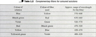
- The simplest filters are either coloured glass or suitably dyed gelatin sandwiched in a glass. They have limited transmission band and are usually complimentary to the color of the solution to be measured.
- The simple filters have a range of 400-680 nm. Table 1.2 shows the filters used for colored solutions. Much more expensive and require more advanced precision instruments.
Diffraction gratings: Most
modern spectrophotometers use diffraction grating method for wavelength
selection. The grating is made of a series of finely etched parallel grooves on
a shining reflecting surface. The grating is placed at an angle to a
Interference filter This is
a more sophisticated type of filter. This filter consists of two partially
transmitting films of metal separated by a transparent spacer of low refractive
index, or of a piece of glass or silicon coated with materials of various
refractive indices.
- The filter is constructed in such a way that only light of the required wavelength is transmitted, all other wavelengths being reflected or absorbed.
- This optical arrangement is called interference. The wavelength of the interference filters is from 330-1200 nm. Interference wedge which acts in a similar way to the interference filters, is not popular because it is costly to produce and it is inferior to diffraction gratings or prisms.
 |
| complementary filter for coloured solution |
Prisms Prisms are composed of glass, for visible
wavelength, and of quartz or silica for the ultraviolet region. They are
designed to be turned to allow the required light to pass through the focusing
slit on to the solution.
- Prism monochromators allow for smaller bandwidths than filters. They are howeverbeam of light. It disperses the white light into a continuous spectrum, each groove acting as a very narrow prism.
- The grating is rotated and wavelength selected by turning the wavelength adjustment.
Note
- Select the correct filter or wavelength for the colored solutions.
- Do not contaminate any part of the optical components as this will adversely affect its performance.
- Do not handle instrument roughly to avoid malfunction. After moving the instrument, recheck the monochro mator and wavelength band.
- Bring instrument to working temperature before use. This is because prisms and filters may be affected by changes in temperature.
C. Solution (Sample) holders
These are used to
hold coloured solutions and must be scrupulously clean.
A number of different holders is available for manual,
semi-automated and automated methods of analysis. The holders can be test-tubes
or cuvettes.
Test tubes These are used
usually in the simpler instruments. They must be matched for transmission;
sometimes a mark is etched on them, and this mark is lined up against a mark on
the instrument to ensure consistent optical pathway.
Cuvettes These are
rectangular cells with one pair of opposite sides optically clear, while the
other parallel sides are opaque and should not be placed in the light path.
They are of glass for use at visible wavelengths, and of silica or quartz for
use in the ultraviolet region.
Flow-through cells These are
used in absorptiometry to speed up analytical procedures. The cells or cuvettes
are drained without being removed from the instruments. In this way, readings
are taken more quickly. These cells are used in automated instruments.
Note
1. No grease, dirt, dried solution or fingerprints should
contaminate the optical surfaces.
2. Rinse the cells
immediately after use.
3. Wipe only with
soft tissue to avoid scratching.
4. Use optically
marked cuvettes.
Optical marking can be done by filling with distilled water
and checking that there is no significant difference be. tween their optical
densities at the wavelength to be used. A difference of not more than 0.002 can
be ig. nored.
D. Photosensitive detector system
There are
three common photosensitive detectors in use--the barrier layer cell, the photo
emissive tube and the photo multiplier tube. When light falls on these elements
electric current is generated this deflects a galvanometer needle. The meter
reading is proportional to the light intensity. These photosensitive detectors
are also referred to as photoelectric cells.
Barrier layer cell this is
made up of a metal disc on which the selenium is thinly layered, and this is
also covered by a thin transparent layer of metal with a thick end to which one
of the terminals of the galvanometer is attached.
- The other terminal is connected to the underside of the disc which is covered by a non-oxidizing metal. With light passing through the thin metal layer to selenium layer beneath, electrons are released which cross the "barrier" between the selenium layer and the transparent metal layer to become positively charged. The current set up is registered on the galvanometer.
A strong incident light
is required for the barrier cell layer since the current produced cannot be
easily amplified. It is therefore usually used in filter instruments where
there is plenty of light energy.
Photoemissive tubes (vacuum
phototubes) These consists of an evacuated glass tube or a tube
containing inert gas at low pressure.
- The inside of the tubes are thinly layered with caesium or potassium oxide and silver oxide to act as the cathode; while the anode is a metal ring inserted close to the centre of the valve.
- Light goes through the valve to reach the sensitive layer and electrons are given off, causing a current to register on the outside circuit which is electronically amplified. This is the amount of light reaching the photosensitive cell. Thus, because the current can be amplified, the photosensitive tube can be used at much lower intensities of light.
- Photo multiplier tubes This is the most sensitive detector which is an improvements of the photo emissive tubes.
- It has enhanced sensitivity because the elements within the tube are connected in series. Light falling on the first element releases secondary electrons in large number resulting in an increase in current flow from the cell.
- It is used in the most sophisticated instrument where it is capable of measuring intensities of light 100 times weaker than those measured by the photo emissive tube.
Note
- Protect detectors from light when not in use.
- Selenium barrier layer cells should not come in contact with mercury or its vapour.
- Detectors should sufficiently "warm up before any reading is taken.
E. Measuring device
The
current from the detector is fed to a sensitive suitable measuring device,
usually a galvanometer. The read-out can be by means of a scale or digital
display. The scale may show both the absorbance and % transmission.
- The absorbance scale ranges from 0 to infinite, while the % transmission scale ranges from 0 to 100. The zero absorbance is equivalent to 100% transmission and the infinitive absorbance is equivalent to transmission.


If you have any queries related medical laboratory science & you are looking for any topic which you have have not found here.. you can comment below... and feedback us if you like over work & Theory
.
Thanks for coming here..